


This procedures describes preparation of cells used for preparing LCE films. Cells are comprised of glass slides separated by spacer. The slides may be coated with an alignment or sacrificial layer, while microspheres, films, and even video camera tape may be used for spacers. Below, procedures for cells permanently with glue and coated with a sacrificial layer are presented.

- balance
- weighing boat | paper
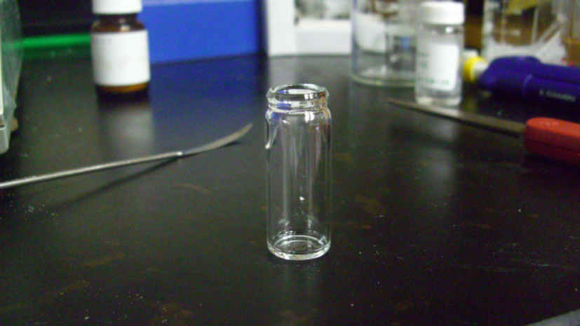
- glass vial | plastic > 5mL
- glass | plastic transfer pipette
- Teflon film (~20um thick)
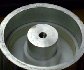
- spin casting head
- heated centrifuge | spinning apparatus
- dry-ice | liquid nitrogen
- Tefzel tape (DuPont)
- 15 cm plastic | wood | metal rod for hanging LCE

nota bene: Before proceeding with this step, the glass should already be coated with the sacrificial layer.

The first step is preparation of the catalyst solution and reaction solution

- Cleanliness is of high priority when making cells. While a clean room is not required, working in a clean environment is. Before starting, have a place to set each glass slide where it will not come in contact with unwanted contaminants. Use gloves when handing the glass.
- Cut the glass to the appropriate size. Typically, 1cm x 1cm or 2cm x 2cm cells are prepared, but any size cell can be used.
- For each cell to be made, cut 2 strips of spacer film. The length of the strip should be about 1cm longer than the lent slide and the width of the strips should be about 2 to 3 mm.
- Wash the glass with successive washes of chloroform, acetone, and then methanol, using an ultrasonic bath if available
- Blow the surface of the glass with filtered, high pressure air. If using glass with a sacrificial layer coated on the surface, be sure to properly identify which side of the glass has the sacrificial coating.
- Place the strips on the surface of the slide as shown in the illustration. The spacer's thickness determines LCE material thickness.
- A cell may be prepared with or without gluing the spacer film to the surface of the slide. (see individual material procedure.) If gluing the strips to the surface of the glass, place a thin coating of glue on the spacer film. Avoid excess glue, as this will spread into the cell when it is assembled. Place the glue coated strip on the surface of the glass and press down firmly. Immediately remove excess glue, glue that has spread from under the spacer film, using acetone or toluene. Allow the glue to dry before proceeding to the next step.
- Place the second cover slide on top of the slide with the spacer strip at a slight offset slightly offset, (~5 to 7 mm). This offset provides an edge for sample loading or a convenient location to solder electrode leads. To insure a tight seal between slides, clamp together or place weight on top of cell.
- If loading the material directly into the cell, (cholesteric LCE) place the bottom cell slide/spacer films directly on the hot stage and place the sample material onto the surface of the slide, then add the second cover slide
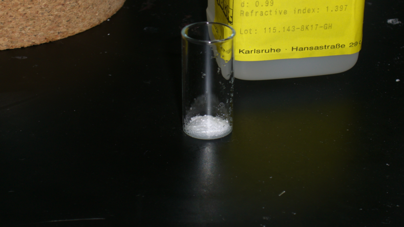
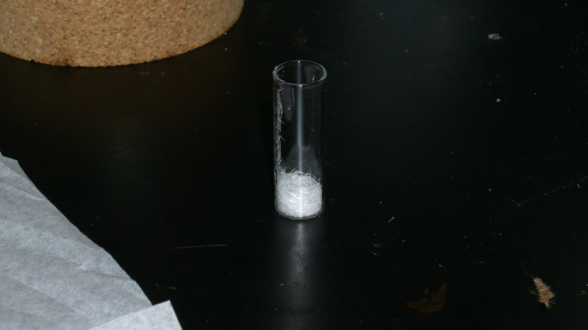
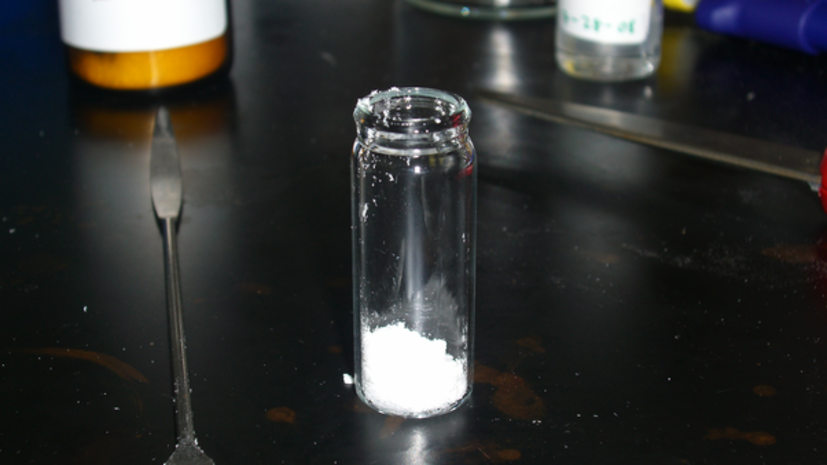
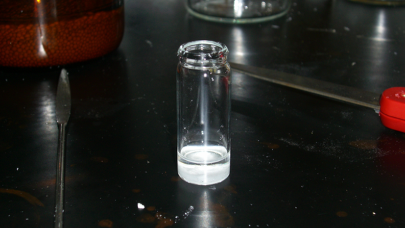
- Materials are transferred to the glass vial in the following order.
- Siloxane polymer - transferred by pipette. Always use the balance to determine the amount of polymer in the vial,
not the amount dispensed from the pipettor.

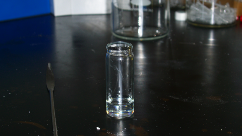
- Cross linker
- Mesogen
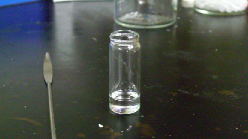
- Siloxane polymer - transferred by pipette. Always use the balance to determine the amount of polymer in the vial,
not the amount dispensed from the pipettor.
This procedures describes preparation of cells used for preparing LCE films. Cells are comprised of glass slides separated by spacer. The slides may be coated with an alignment or sacrificial layer, while microspheres, films, and even video camera tape may be used for spacers. Below, procedures for cells permanently with glue and coated with a sacrificial layer are presented.